THE TRANSMITTER CONSTRUCTION:
The circuit board consists on 1,5 mm Epoxy base material of double sided concealed.
The upper side offers an almost universal mass surface.
If no through contacted circuit board is used, leading prefabricated parts must be soldered after mass in principle also on the mass side.
The 20 mm tall outside wrap of the Semi Rigid Cable and a side of the inside leader is soldered flat with the mass-side.
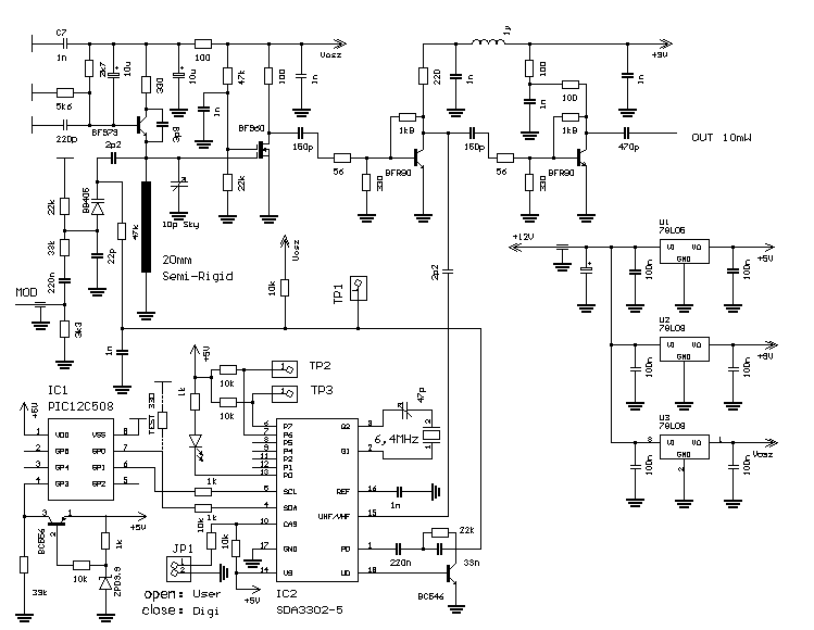
The two BFR90 are installed with the labeling downward. The labeling of the BF979 and the BF960 shows upward mass-side. The Drain-Connection of the BF960 is marked by a longer connection leg. The Source-Connection of the BF960 should lead with circuit boards without through-contact on the shortest way to the mass-side and soldered there. The SDA3302-5, one may not equip with setting. As output-terminal, a BNC-connector can be used.
One installs C13 between method-pin of the socket with the circuit board externally directly then. A SMC or SMA-Beech, that is soldered directly on the leader-track, is also possible for example electrically sure favorable, but these sockets are not so current.
THE TRANSMITTER TUNE UP:
In order to enable Frequency measurement at the test points 2 and 3, the PLL IC must be switched into a test mode.
A 330 ohm resistance becomes externally soldered from pin 7 of the PIC12C508 to mass on the circuit board-underside.
In the diagrams, this resistance is marked as R TEST. After taken place tune-up don't forget the unsoldering of the resistance.
As next, the application of the transmitter definitely turns JP1 with Jumper for User or Digipeater.
For the operation with the User 434,900 MHz must be pulled the Jumper.
The care tension, on which the programming of the PLL IC takes place through the PIC, is positioned now first.
With faulty programming, LED D2 shines. If everything is in order, it flashes only shortly and stays away then.
At TP2, the phase comparison frequency of the PLL is to be done as TTL rectangle signal.
With Trimmer C24 is balanced the frequency on 12,5 kHz.
On no account, one should try to measure the frequency of the 6,4 MHz quartz directly.
This swings would be detuned also with a good touch head too much into series-resonance and its vibration frequency.
The AVC voltage of the PLL is available at TP1.
When the slow spinning the Sky Trimmers C10 should have gotten ready these for 4 to 5V.
The Trimmer on this occasion virtually stands in middle position.
If the avc voltage lies about 9V, so the frequency of the VCO, that Trimmer must, become out turn too deeply further.
If she lies over 0V barely, so the capacity of the Trimmers must be increased.
The tune up of the transmitter is already finished with it.
The VCO-Frequency divided through the PLL-IC can be removed at TP3.
With arranging varieties from the PLL, 12,5 kHz are also to be done here.
The test-point is not necessary to the tune up, with a possibly necessary debugging can be checked here however also without 500 MHz counters, whether and where the VCO swings.
The division factor of the PLL with user operation amounts to 34792.
In order to reach a mould of the output-spectrum of at least 40dB at the channel-borders, the lifting may not be bigger than 25 - 30 kHz with a baud rate of 76,8 kBaud.
In order to avoid disturbances in the neighbor channel, the modulation tension should be put in at the modem output smaller than 500 mVss.
With our pattern constructions, we have measured following collector, as well as Drain tensions in the method: T1 6V, T2 8V, T3 5,2V, T4 4,2V.
The output power lay with all based prototypes over 10 MW.
|